Calculus of Soft Trustworthiness
Presented in TAS node in Functionality Seminar, 2022.
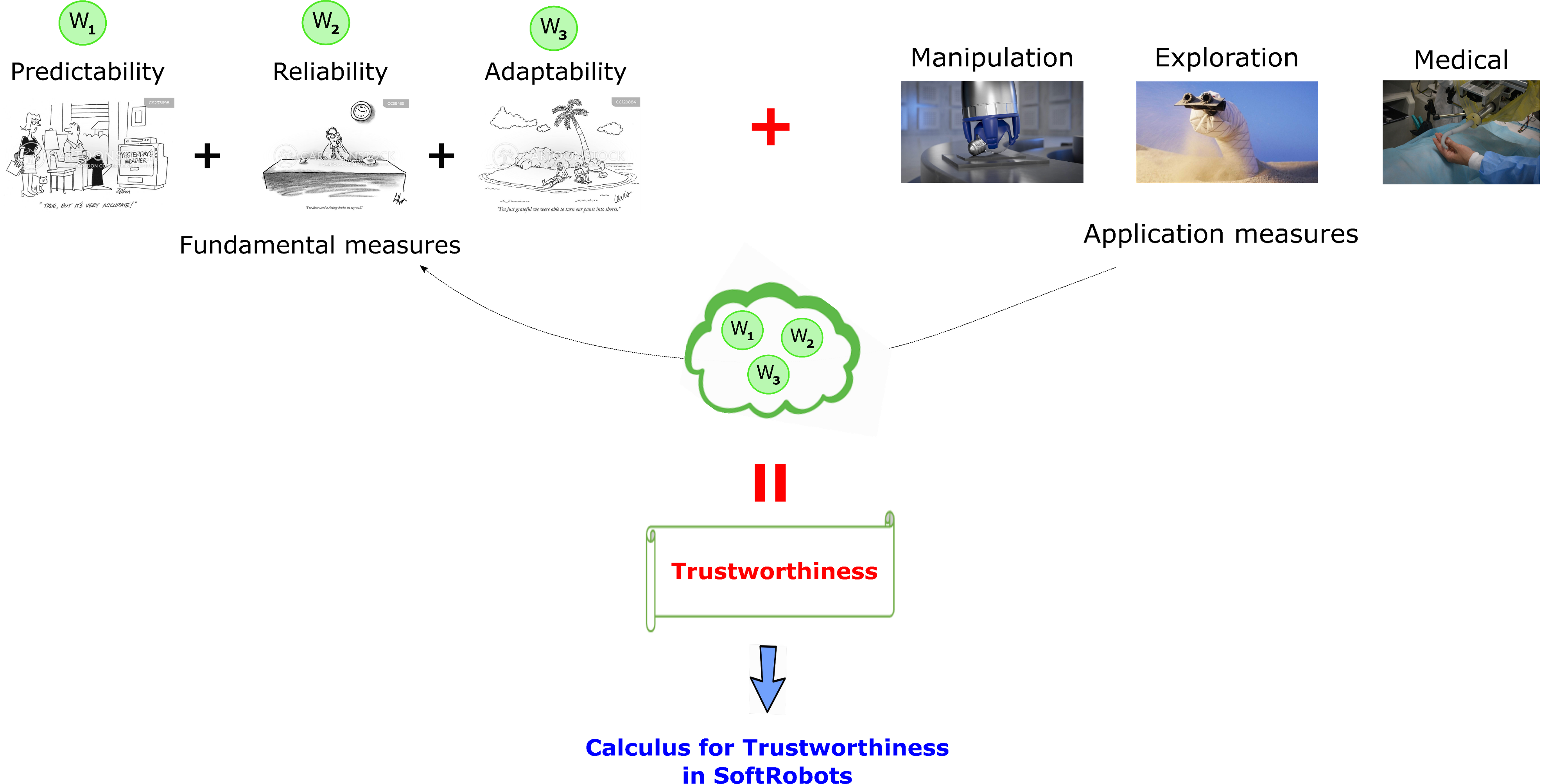
Due to the inherent uncertainty in soft robot systems, it is a challenge to quantify trustworthiness in soft robots. In addition, there is not a universal definition for what constitute as a trustworthy soft robot in the field. Bear in mind these challenges I propose a universal framework to calculate Trustworthiness in Soft-robots which consists of application measures and fundamental measures. The Fundamental measures can be predictability, reliability or adaptability.
Applications measures can be manipulation, exploration or medical. Application measures dictate the weighting for fundamental measures of trust worthiness. i.e. different application has specific requirements in terms of predictability, reliability and adaptability.
Manipulation → focus more strongly on predictability
Exploration → more focus on adaptability
Medical → more focus on reliability
We believe that Trustworthiness in soft robot is application driven. As such, I decided to explore predictability of soft gripper in manipulation application as a first function for my calculus.
I am taking a top-down approach with an initial focus on predictability to describe and quantify trustworthiness. I also think that predictability might be inversely proportionate in certain cases to adaptability as the robot is less adaptive when predictability increase. To achieve this, I am going back to the basics of soft robotics and ask myself a question: what is the fundamental building blocks of soft robots?
Soft robots are made of soft elements that bend, twist or extend which are the fundamental behaviour of soft robots. As such, I am looking at the buckling effect of cylindrical shapes with different cross-sectional areas (I call these simple soft elements morphels). I choose to investigate these morphels because they are simple, having a particular behaviour (bending) and offer good flexibility and control. By investigate the buckling behaviour of these morphels, I can hopefully quantify the trustworthiness of soft robots. I call this Calculus of soft trustworthiness.
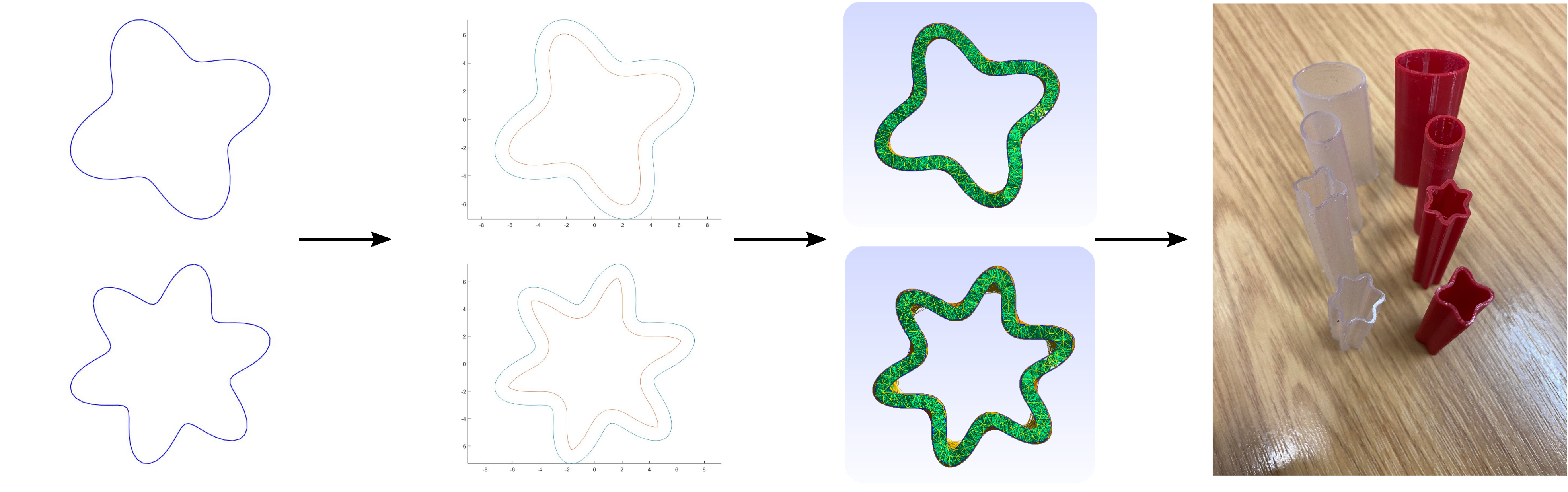
Here is the entire morphels design process from initial sinusoidal family shapes descriptor to wall thickness calculation to 3D volumetric shapes generation and finally the end product through 3D printing.
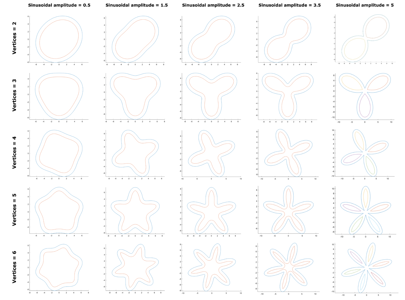
Regarding the morphels design, I have developed a function to describe a sinusoidal family of shapes. This function takes perfect circle as their root, and by varying number of waveforms and the magnitude of the wave amplitude, I am able to generate a range of sinusoidal shapes which could output interesting buckling behaviors. To be able to generate the 3D volumetric shape of these morphels, I gave these shapes a wall thickness of 1mm.
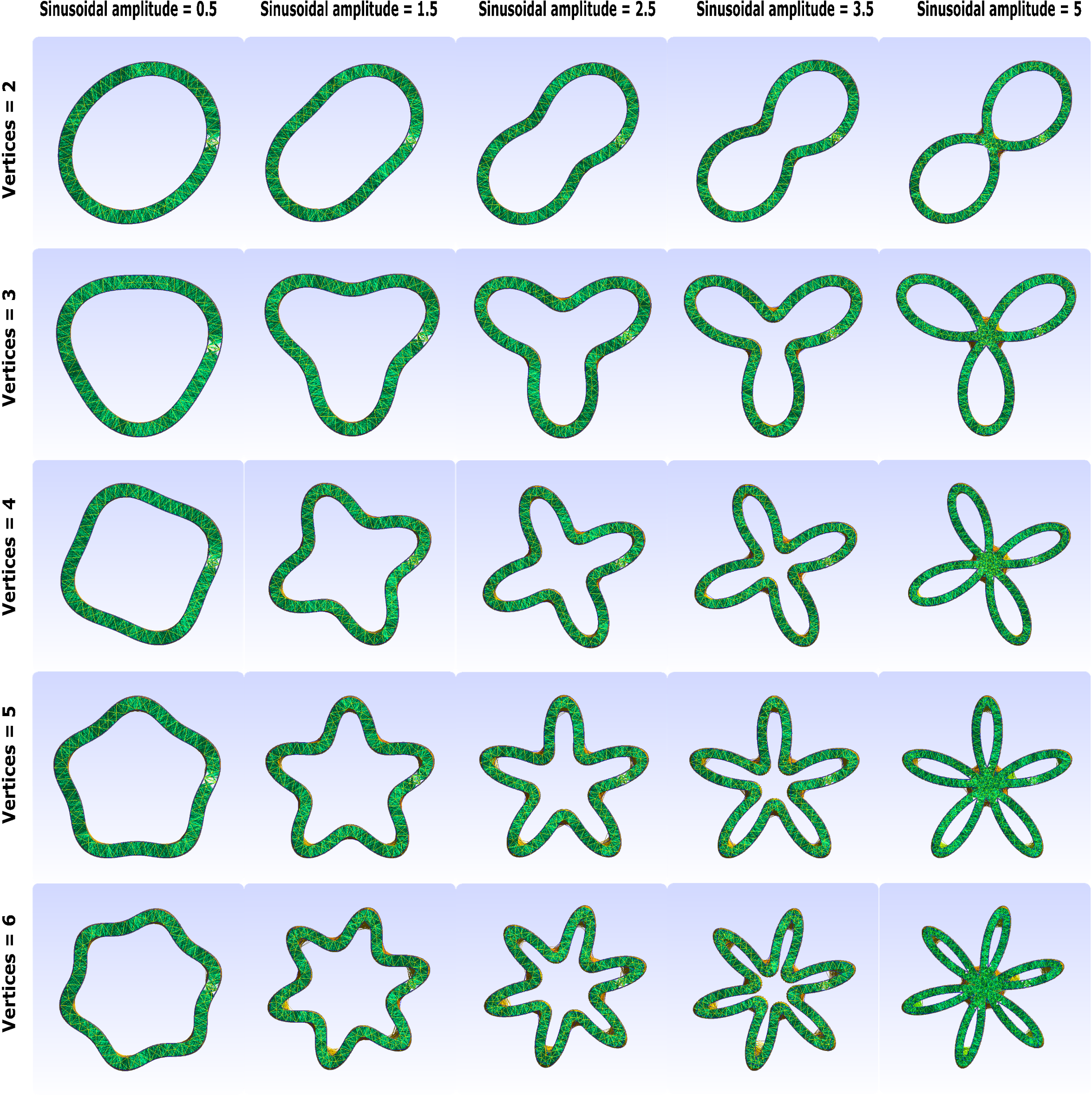
Here is the 3D volumetric shapes generated by gmsh for the above sinusoidal shape family.
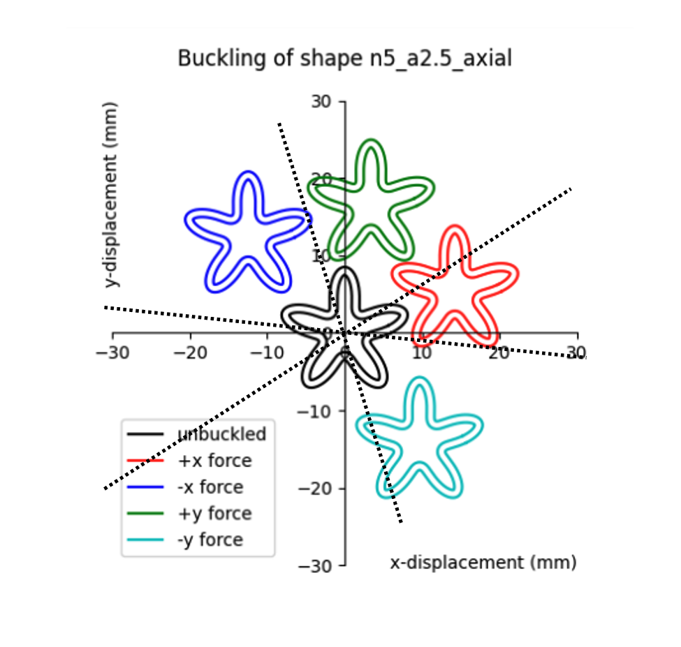
This plot is showing you the average end position of the buckling of the shape depending on which bias force is acting on it. Note that the colour curves are just representation of the shape not the actual cross-sectional area of the buckled shape. It is clear from the plot that the buckling happens at the principal axes of the shape (represent by black dotted lines) under the influence of the bias forces. This is what we normally expect. However, this behaviour is not quite true as the vertices and amplitude increase. I will clarify this point in the next slide.
I decided to use SOFA because SOFA can batch process thousands of possible scenarios. It is a powerful simulation tool to quickly narrow the massive search space and focus on important geometries. This is a SOFA simulation set-up for the pentafoil shape.
This particular shape has 5 vertices and the sinusoidal amplitude applied on the shape is 5mm. The shape is fixed at one end and an axial displacement (z-axis direction) of 20mm is applied to the other end to simulation compression force.
The red boxes are called region of interests or ROI boxes. They are used to applied constraint and/or monitor the mechanical behaviour of the elements trapped within the region of interest boxes. I used the red box in the middle to track the displacements of all the elements within it because the buckling tend to happen at the middle of the cylinder.
The simulation time step is 0.1s which correspond to a displacement of 0.1mm. Currently, a set of 4 simulation is run for each scenario, each simulation a small bias force of 100mN is applied to all the elements within the middle ROI box to replicate imperfections cause the fabrication process in real life. The bias forces are applied in plus, minus x and y directions.
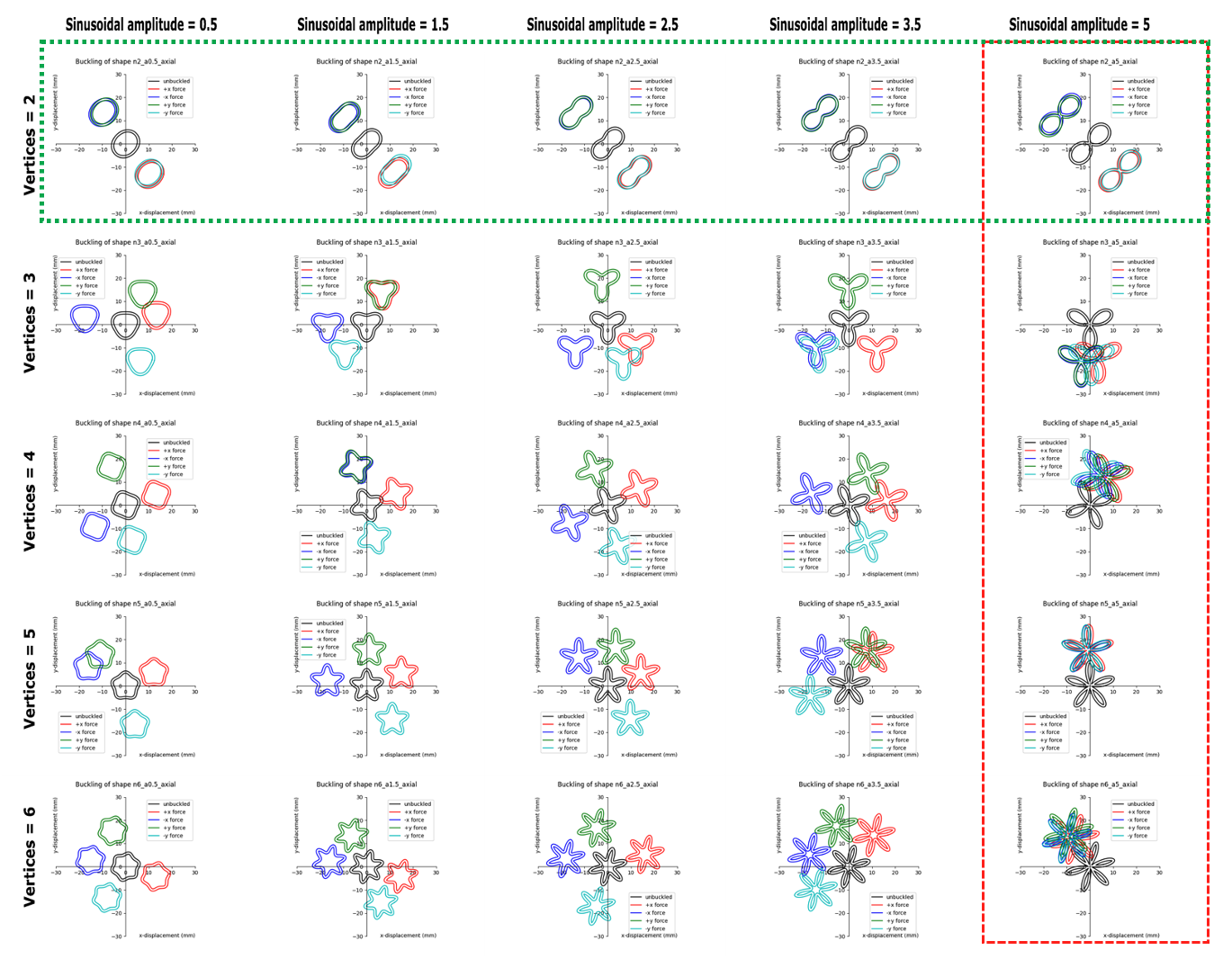
Here is the buckling plot of all simulated shapes. As you can see, at low vertices and amplitudes the buckling tend to happen at the principal axes of the shapes. As can be seen in the dotted green box, depending on the bias forces applied, the shape would buckle up or down. However, as the vertices and amplitude increase, the buckling direction becomes more and more independent from the bias forces applied. We can see from this dotted red box, all the buckling tend to happen at the same orientation.
Bellow is a test rig build to validate the buckling behaviour of the simulated shapes. The results collected from the test rig seems to agree with the simulation results.